

Arduino LED Knight Rider Pattern ?
Arduino LED Knight Rider | Today we are going to create awesome knight rider circuit with Arduino. No need any special electronic skills.
History of Knight Rider
Knight Rider is an American action crime drama television series created and produced by Glen A. Larson. There is a car in this series called KITT (Knight Industries Two Thousand). The speciality of this car is it’s an AI ( Artificial intelligence ) embedded car. Also it can talk with people and also there are some interesting features such as autopilot, decision making and many more. As a 90’s kid there is something special about the car for me. It is the knight rider car light system. I think it’s special not just for me. Every single kid loved it those days as I remember.
However, today we are going to build this light system with Arduino. Arduino is an open-source physical computing platform based on a simple I/O board and a development environment that implements the Processing/Wiring language. Arduino can be used to develop stand-alone interactive objects or can be connected to software on your computer (e.g. Flash, Processing and MaxMSP). The boards can be assembled by hand or purchased pre-assembled, the open-source IDE can be downloaded for free at. And you can check the official site here.
Requirements
- A arduino board ( Uno or Mega )
- Breadboard
- 6 LED Bulbs
- 6 100 ohm Resistors
- Some jumper cables
Note :- If you do not have the above components in hand, don’t worry you can try all examples out in a virtual environment. You can simply google “Arduino online simulator”. You will have a 100s of results. Some of them are free and some of them are not for free. In my case I used the Tinkercad simulator for my tutorials. You also can check this out using the URL below.
Table of Content :
Let's Begin the Arduino LED Knight Rider journey.
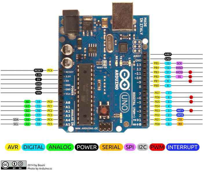
Image source :- From Arcuino.cc
01. Simple 01 Arduino LED Blink Circuit .
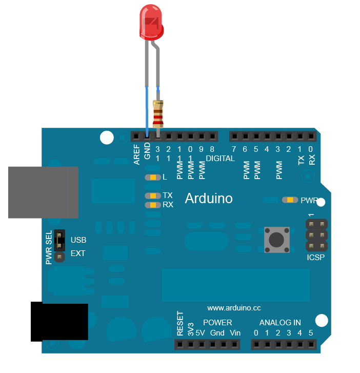
If you are a beginner or new to Arduino, I think this example will be a good start on your journey. In this example we are going to make a simple Blink LED. You just need a single LED and a breadboard and some jumper cables and 100 ohm resistor only. First we have to make our circuit on the breadboard.
Coding part
I used c++ to code the micro controller ( Arduino board ) and I used the 13’th pin as the output PIN. You can use any digital pin for this. I attached the Arduino UNO board pinout above, check it if you want to know about the pinouts of UNO.
// C++ code
void setup(){
  pinMode(13, OUTPUT);
}

void loop(){
  digitalWrite(13, HIGH);
  delay(1000); // Wait for 1000 millisecond(s)
  digitalWrite(13, LOW);
  delay(1000); // Wait for 1000 millisecond(s)
}
OUTPUT
How does it work ?
In the setup function, we set the 13th pin as our output pin. Which means we use this pin as our anode ( + ) . In simple words we use this 13th pin to give commands ( power ) to the LED.
Then in the loop function,
This supplies 5 volts to the LED anode. That creates a voltage difference across the pins of the LED, and lights it up. Then takes the 13th pin back to 0 volts, and turns the LED off. In between the on and the off, you want enough time for a person to see the change, so the delay() commands tell the board to do nothing for 1000 milliseconds, or one second. When you use the delay() command, nothing else happens for that amount of time.
HIGH -> 1 -> ON
LOW -> 0 -> OFF
02.Build Arduino LED Knight Rider Circuit for Digital.
You can download the circuit diagram from here.
Summery :-
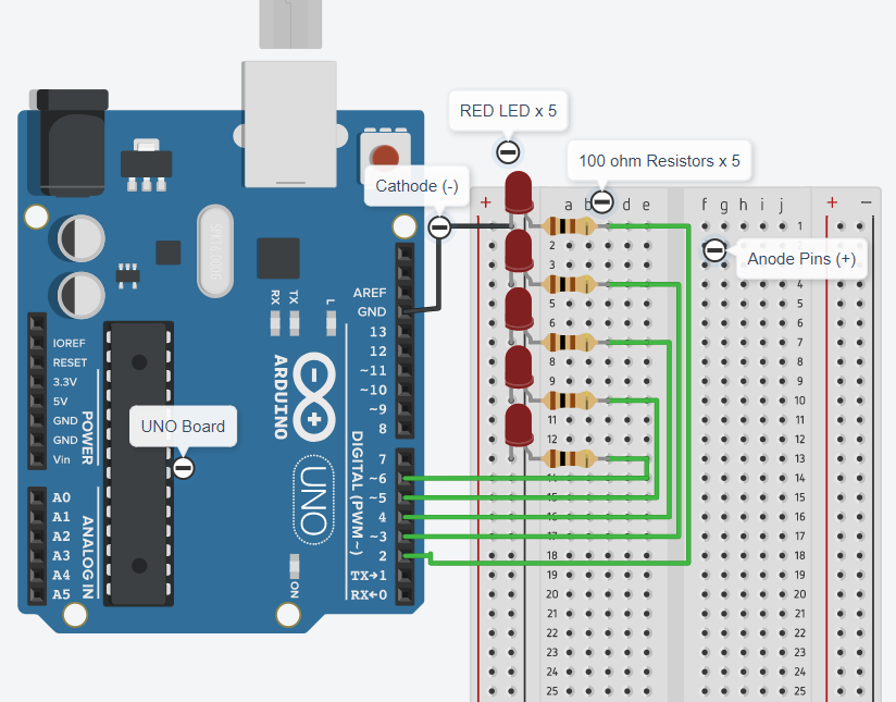
- RED LED x 5
- 100 ohm Resistors x 5
- Arduino UNO Board
- Bread Board
- Jumper Cables
We connected all the cathode pins of LED’s together and then set it with the GND ( ground ) pin in the Arduino Board. Then set 2,3,4,5,6 pins with the LED’s anode pins respectively. Also used 100 ohm Resistors between anode and Arduino board pins.
03.Program the Arduino - pattern 01 ( Digital )
First we have to set the 5 pins as OUTPUT. In this case we use digital pins. So I use 2, 3, 4, 5 and 6 pins as our output pins. It is hard to set pinMode one by one. So I use an array to contain my pins and It will help me in future to make the code easy and short.
int pinouts[] = {2,3,4,5,6};
Then we have to set the pinMode for the above pins.
void setup(){

  for(int i=0;i<5;i++){
    pinMode(pinouts[i], OUTPUT);
  }

}
Now is the time to add a pattern ( Up and Down ).
void loop(){

  for(int i=0;i<5;i++){
    digitalWrite(pinouts[i], HIGH);
    delay(100); // Wait for 100 millisecond(s)
    digitalWrite(pinouts[i], LOW);
    delay(100); // Wait for 100 millisecond(s)
  }

  for(int j=5;j>0;j--){
    digitalWrite(pinouts[j], HIGH);
    delay(100); // Wait for 100 millisecond(s)
    digitalWrite(pinouts[j], LOW);
    delay(100); // Wait for 100 millisecond(s)
  }

}
Full Script for Arduino LED Knight Rider Circuit :-
int pinouts[] = {2,3,4,5,6};

void setup(){
  for(int i=0;i<5;i++){
    pinMode(pinouts[i], OUTPUT);
  }
}

void loop(){

  for(int i=0;i<5;i++){
    digitalWrite(pinouts[i], HIGH);
    delay(100); // Wait for 100 millisecond(s)
    digitalWrite(pinouts[i], LOW);
    delay(100); // Wait for 100 millisecond(s)
  }

  for(int j=5;j>0;j--){
    digitalWrite(pinouts[j], HIGH);
    delay(100); // Wait for 100 millisecond(s)
    digitalWrite(pinouts[j], LOW);
    delay(100); // Wait for 100 millisecond(s)
  }

}
OUTPUT - Arduino LED Pattern 01

04.Build Arduino LED Knight Rider Circuit for Analog.
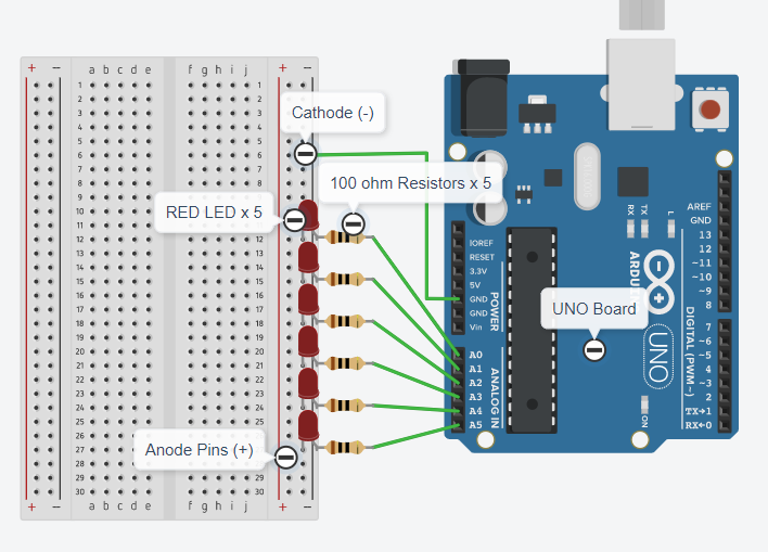
Summery :-
- RED LED x 6
- 100 ohm Resistors x 6
- Arduino UNO Board
- Bread Board
- Jumper Cables
We connected all the cathode pins of LED’s together and then set it with the GND ( ground ) pin in the Arduino Board. Then set A0,A1,A2,A3,A4,A5 pins with the LED’s anode pins respectively. Also used 100 ohm Resistors between anode and Arduino board pins.
05.Program the arduino - pattern 02 ( Analog )
First we have to set the 5 pins as OUTPUT. In this case we use digital pins. So I use A0,A1,A2,A3,A4 and A5 pins as our output pins. It is hard to set pinMode one by one. So I use an array to contain my pins and It will help me in future to make the code easy and short.
int myPins[] = {A0, A1, A2 , A3 , A4, A5 };
Then we have to set the pinMode for the above pins.
void setup(){
  for(int i=0;i<5;i++){
    pinMode(myPins[i], OUTPUT);
  }
}
Now is the time to add a pattern ( Up and Down ).
void loop(){

    for(int i=0;i<6;i++){
        for(int j=255;j>=0;j-=100){
          analogWrite(myPins[i], j);
          delay(10);
        }
        delay(50);
    }
    for(int i=5;i>0;i--){
        for(int j=255;j>=0;j-=100){
          analogWrite(myPins[i], j);
          delay(10);
        }
        delay(50);
    }

}
Full Script for Arduino LED Knight Rider Circuit :-
int myPins[] = {A0, A1, A2 , A3 , A4, A5 };

void setup(){
 for(int i=0;i<5;i++){
    pinMode(myPins[i], OUTPUT);
  }
}

void loop(){

  for(int i=0;i<6;i++){
    for(int j=255;j>=0;j-=100){
      analogWrite(myPins[i], j);
      delay(10);
    }
    delay(50);
  }

  for(int i=5;i>0;i--){
    for(int j=255;j>=0;j-=100){
      analogWrite(myPins[i], j);
      delay(10);
    }
    delay(50);
  }

}
OUTPUT - Arduino LED Pattern 02

Ask any question that you have in the contact section. Thank you!